EBSD Data for Dream3D
Purpose
The purpose of this post is to outline the flow of information from a 2-D Electron Backscatter Diffraction (EBSD) scan to Dream3D for generating 3D microstructures for Finite Element Method (FEM) Simulations. This is from the perspective of the EBSD user to output data in a usable format for Stats Generator in Dream3D.
Steps
- Collect EBSD map. Size matters - the scan should include enough grains so that statistics are representative of the sample.
- Cleanup (Optional).
- Compute grain size distribution, misorientation distribution, and the orientation distribution function (ODF).
- Create a 3D microstructure in Dream3D based on the microstructure statistics.
Step 1
This data was collected on a field emission scanning electron microscope (Tescan Mira XMH FE-SEM) equiped with a backscatter diffraction detector (EDAX Hikari) with OIM Data Collection Software. Important information includes Beam Voltage, Beam Intensity, Working Distance,Step Size, etc. This information is typically in the summary of the scan. The material is Ti-6Al-4V which with a beta annealled heat treatment. Both alpha and beta crystal phases were selected. The EBSD scan can be visualized as an inverse pole figure IPF map where the color represents the crystal plane normal that is parallel with the surface normal or with an Bunge Euler angle plot where the color represents the location in the Euler angle space. All analysis and plots were done using OIM Analysis Software.
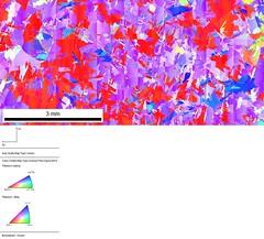
IPF Map

Bunge Euler Angle Map
The raw data (currently not usable in Stats Generator) can be saved in the form of an .ang file which can be read as a text file. This step is necessary if you plan to use or analyze the data outside of OIM Analysis Software.
Step 2
Cleanup was done on data points which did not belong to a grain with a size of 10 microns or more. These data points were iteratively assigned to existing grains using the Grain Dilation procedue in OIM Analysis. For this example, we were only concerned with the alpha phase. * Grains in EBSD are groups of similarly oriented points. A grain tolerance angle is specified such that the nearest neighbors don’t exceed this tolerance value. This means there is a very small misorienttion spread between closely neighboring points, but a single grain composed of many points could have a much larger misorientation spread. A minimum grain size is also specified. Points which don’t meet the neighbor tolerance angle of a grain greater than or equal to the minimum grain size are not assigned to a grain. * Grain size is given as a diameter. The diameter is computed by inserting the area of the grain into the area equation for a circle and solving for the diameter.
Step 3
Statistics
- Grain Size Distribution
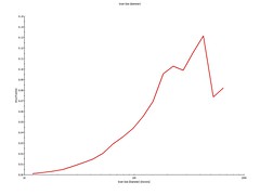
The historgram can be exported to a text file.
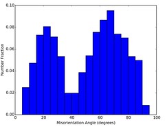
- Misorientatin Distribution (misorientation angle between boundaries)
The historgram can be exported to a text file.
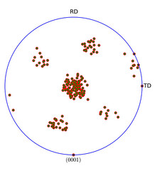
- Orientation Distribution Function (ODF) and Key
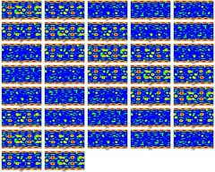
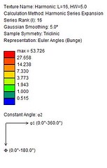
The ODF can be calculated using different methods; however, the most common method is the harmonic series expansion. The ODF is a compact way of representing the material’s texture as a function.
Currently, Dream3D is limited to euler angle sets, intensity (mutliple times random), and spread (???) for specifiying the ODF. Suggested protocol
- Limit the euler angles based on crystal symmetry (The ODF is periodic). For hexagonal crystal symmerty the range is: 0 to 2pi, 0 to pi/2, 0 to pi/3 for phi1, Phi, phi2 respectively.
- Limit the angles based on a minimum intensity. Maybe a value of 2 or greater. An intensity of 1 is equalivalent to a random texture.
- Choose one spread value. Maybe 5 because of 5 degree spacing in calculating the ODF?
- Enter in the euler angle sets that are left. The maximum number of entries is 5,000 lines.
Another way for small scans (less than 5,000 points) is to enter every point (minus “bad” points) with equal intensity and spread.
Step 4
Once you have the statistics, this presentation outlines the step-by-step procedure in the Dream3D software package.
Current Microstructures from Dream3D
We are currently working with the Dream3D Team to fix some errors in their implementation; below is a detailed account of our current implementation and areas that need correcting.
- The grain size distribution is fit to a log-normal distribution (via SigmaPlot) and the $ \mu $ and $ \sigma $ values are used in StatsGenerator. Unfortuantely, their log-normal plot with $ \mu $ and $ \sigma $ is not for all grain size values greater than zero; it cuts off grains smaller than ~200 microns (in diameter). That is unfortunate for us because our grain size for Ti-64$\beta$ ranges from 10 to 600 microns. They are aware of this discrepancy and are working to fix it.
- The ODF import function in Dream3D cannot currently import .ang files, but that is something they are currently working on it. Instead, I have found that a the pole figures can be approximated by simply entering the euler angles with highest intensity and varying the weights/spreads to match the experimental pole figures.
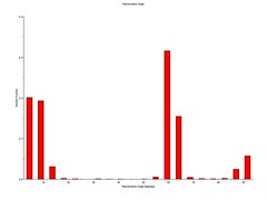
- The MDF import function contains an error that miscalculates the frequency in the misorientation histogram. Dream3D is aware of this error and is currently fixing it.