CSM corrections to load, displacement, and contact stiffness revisited
Background
Pharr et al. (2009) investigated and proposed corrections to the load, displacement, and contact stiffness for nanoindentation tests using the continuous stiffness measurement/module (CSM). The effect of these corrections on the indentation stress-strain analysis developed by Kalidindi and Pathak (2008) was explored by Vachhani et al. (2013). While the conclusions drawn by Vachhani et al. (2013) are correct, we will revisit the CSM corrections in light of developing a path to automate the indentation stress-strain analysis.
The new question is: How do the CSM corrections effect the automation or optimization of the zero point correction and indentation stress-strain curve?
See previous posts:
Nanoindentaiton Stress-Strain Analysis Automation
Importance of CSM to ISS Analysis
Theory
The corrections to load and displacement are:
Where the subscripts and represent the actual and apparent or machine recorded values respectively. and are the peak-to-peak load and displacement amplitudes of the superimposed oscillatory (AC) signal used with CSM. Note that recent methods in Nanosuite for Agilent G200 XP head indenters have applied these correction to load on sample and displacement into surface.
More useful expressions are
Where and are the root mean squared values of the load and displacement oscillations and the channels harmonic load and harmonic displacement
The correction to harmonic contact stiffness is:
Where , , and .
Taping is a fourth error Tapping occurs during the initial stage of contact where the tip engages the sample but lifts back off the sample. Tapping is implicitly accounted for in the harmonic contact stiffness correction.
Which causes to be undefined when the ratio is greater than one. That is
so that tapping does not occur.
Results
The concept of a zero point correction is most easily viewed by plotting and against displacement or time.
Without harmonic corrections applied, the terms look like this

The zero point correction , brings , , and in agreement with Hertz Theory.
If we then apply the CSM corrections, it looks like this
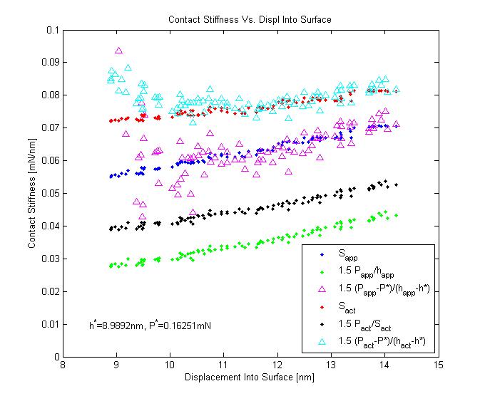
Note that the CSM correction to load and displacement does not bring it in agreement with the apparent stiffness . Furthermore when comparing it to the actual stiffness , the gap is even further. Hence, the zero point correction is still needed. In fact the same zero point determined from , , and appears to bring , , and in agreement. This supports the finding that the indentation stress-strain curve is not sensitive to the CSM corrections as seen by Vachhani et al. (2013). Note her conclusion is based on more proof than this so please see the paper for full details.
If we are interested in tapping, we can plot and

We see that most if not all of the data selected for determining the zero point correction also satisfies Equation 7 (i.e. tapping is certainly not occurring).
Indentation Stress-Strain Curve
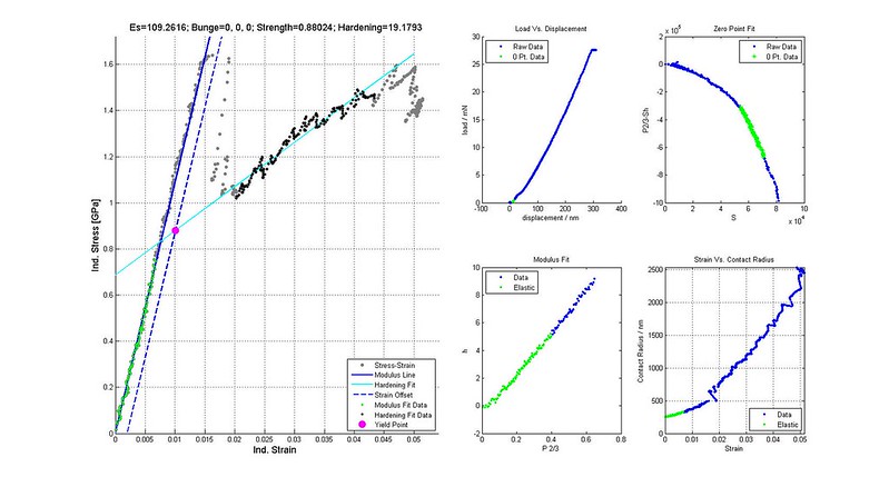
The data highlighted in green was selected for determining the zero point correction and effective modulus. This is the indentation stress-strain curve without CSM corrections.
Discussion and Conclusion
-
The CSM corrections have an effect on the zero point fit evaluation (r-squared, maximum absolute residual, etc). If we are using these values to select the best analysis or analyses, the CSM corrections will have some effect on the selection.
-
Errors in the apparent load, displacement, and contact stiffness are well documented and understood. There is no reason not to correct for them even if they cause little change to the indentation stress-strain curve.
-
The data discarded when correcting the harmonic stiffness represents unreliable data because the indenter may be tapping (engaging and lifting off) the surface. In fact, we can use this to inform our zero point correction determination and limit the possible segment selections.
- Should be recalculated after the zero point correction is determined i.e based on ?
- First, the machine zero point only effects the load and displacement. It has no influence on the harmonic load, harmonic displacement, and contact stiffness.
- Secondly, this zero point produces a consitent starting point at which the load, harmonic load, and contact stiffness are all approximately zero and start to increase upon contact. Another way of saying this is the load used in the correction of should have the same zero point ast .
- Lastly, the zero point correction used to calculate indentation stress-strain curves is an effective zero point and not necessarily the actual point of contact.
- Therefore, it makes sense to use the load determined from the machine zero point for correcitng the contact stiffness, and this is a one time calculation.
- Some cases may arise where the data discarded during the CSM correction to contact stiffness is critical for the zero point correction and indentation stress-strain curve. This could be avoided by adjusting the machine zero point so that more data satisfies Equation 7. However, this adjustment should be justified (i.e. the machine zero point was clearly wrong and/or the data provides reliable and quality indentation stress-strain curves).
####In conclusion, I propose CSM corrections to the apparent load, displacement, and contact stiffness signals before the zero point correction and stress-strain curve is calculated.####
References
Pharr, G.M., J.H. Strader, and W.C. Oliver. “Critical issues in making small-depth mechanical property measurements by nanoindentation with continuous stiffness measurement.” J. Mater. Res. 2009
Kalidindi, S.R. and S. Pathak. “Determination of the effective zero-point and the extraction of spherical nanoindentation stress–strain curves.” Acta Materialia. 2008.
Vachhani, S.J., R.D. Doherty, and S.R. Kalidindi. “Effect of the continuous stiffness measurement on the mechanical properties extracted using spherical nanoindentation.” Acta Materialia. 2013
Data
Click here to access the raw data and some additional files.
The analysis and plotting was done in Matlab.
Experiment Details
A 16.5 micron conical spherical diamond tip was used on an Agilent G200 nanoindenter with the XP head. The basic CSM test method was used with 2nm, 24Hz and a target strain rate of 0.05 s-1. The sample was commercially pure titanium with an electropolished surface mounted in epoxy.