Importance of Frame Stiffness for High Load Nanoindentation
Purpose
Larger radii tips and higher loads than previously used are needed in order to get effective properties (probing multiple microscale features) and explore indentation size effects on the indentation stress-strain response. In the process of doing these experiments, it became apparent that the harmonic contact stiffness, displacement into surface, and subsequently indentation stress-strain curve are sensitive to the frame stiffness.
Background
For an Agilent G200 nanoindenter with an XP head the system is well described by a system of springs, dampers, and a mass (simple harmonic oscillator) [1]. One of the springs in the system is the frame stiffness which is typical for any mechanical tester. The frame stiffness is typically determined from indenting fused silica with a Berkovich tip and doing a regression analysis to determine the area function and frame stiffness simultaneously to minimize the error between the known modulus and the measured modulus. The specification for frame stiffness is . Typical values range from to N/m.
The frame stiffness can vary based on the tip, sample tray and location, and mounting procedure. For example based on tray location it can range from 6.5 to 9.9 N/m [1]. Additionally it is recommended to determine the frame stiffness for a specific experiment when the harmonic stiffness is 10% or greater than the frame stiffness [1].
Two equations that are important here are harmonic contact stiffness and displacement into surface .
Variables
- harmonic stiffness straight from CSM
- frame stiffness
- raw displacement
- raw displacement at the test zero point
- thermal drift correction
- time on sample
- Load on sample
Three other specifications that are important
- XP head Max Load 500mN [1]
- High Load Option Max Load 10N [1]
- XP head Max Harmonic Load 5mN [2]
Results
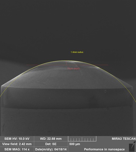
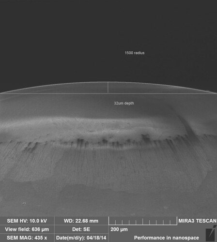
In these experiments a spherical diamond tip with a nominal radius of 1500 microns was indented on electropolished Ti-6Al-4V with a annealed microstructure. Tests with and without CSM were run with High Load Methods.
The tip geometry was verified with SEM images
The sample was mounted in epoxy and a sample tray was made for going from the indenter to the SEM. The frame stiffness determined from indents on fused silica with a Berkovich tip was N/m. A guess at the correct frame stiffness was made as N/m.
Load-Displacement and Stress-Strain Analysis with CSM
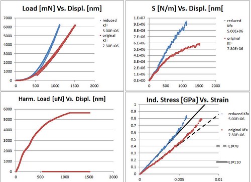
- First, the indent is mostly elastic which can be seen by the recovery during unloading.
- The difference in frame stiffness has a large effect on the load-displacement curve as well as harmonic contact stiffness.
- The harmonic load limit (5mN) is reached well before the load limit (10N) load.
- The lower frame stiffness gives the correct sample modulus ~110 GPa for the indentation stress-strain analysis [3].
- Data in the stress-strain curve is cut at the harmonic load limit (5mN). Data past this limit further deviates from the modulus line on the left. It is not clear why this occurs but data near the limit may not be reliable.
Load-Displacement and Stress-Strain Analysis with CSM
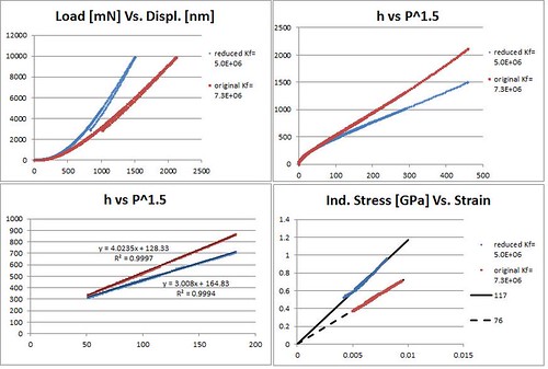
- Again the indent is mostly elastic. There is some visible plasticity in the final unload. There are many unloads at increasing loads prior that fall on top of each other.
- A plot of Vs. shows the expected linear relationship for elastic contact described by Hertz Theory and the effective modulus can be determined from a linear regression.
- Again the effect of the frame stiffness is apparent in the differences between to the two curves, and the correct sample modulus (117 GPa) can be obtained using a lower frame stiffness.
- Note only a displacement correction was used (the y-intercept of the linear regress) and only the data used in the linear regress was converted to stress and strain.
Conclusions
- The frame stiffness is likely lower than the currently calibrated value.
- We have reached a contact radius of 30-40 microns under elastic loading which is large enough to get effective properties for single colonies in the Ti64 annealed microstructure.
- Plasticity occurs too close to the harmonic load and monotonic load limits such that indentation strength is unobtainable for these experiments.
- A smaller tip and/or using the microindenter will address this problem.
References
- “Agilent Technologies Nano Indenter G200 User’s Guide.” Agilent Technologies, Inc. Ed. Rev C. 2012
- Agilent Continuous Stiffness Measurement(CSM) Option
- Kalidindi, S.R. and S. Pathak. “Determination of the effective zero-point and the extraction of spherical nanoindentation stress–strain curves.” Acta Materialia. 2008.