Indentation Sample Displacement and Eeff vs Eind
Background
Hertz theory describes the elastic, frictionless contact between two isotropic materials with parabolic surfaces. In the case of spherical nanoindentation we have a diamond spherical indenter ($i$) and a flat sample ($s$). In this case Hertz Equation takes the following form:
\begin{equation} a=\sqrt{R_{eff}h} \end{equation}
\begin{equation} \frac{1}{R_{eff} }= \frac{1}{R_i} + \frac{1}{R_s} \end{equation}
The indenter properties are $E_i = 1140 GPa$ and $\nu_i = 0.07$, and the sample radius of curvature is $R_s = \infty$ making $R_{eff} = R_i$ provided that no plastic deformation occurs.
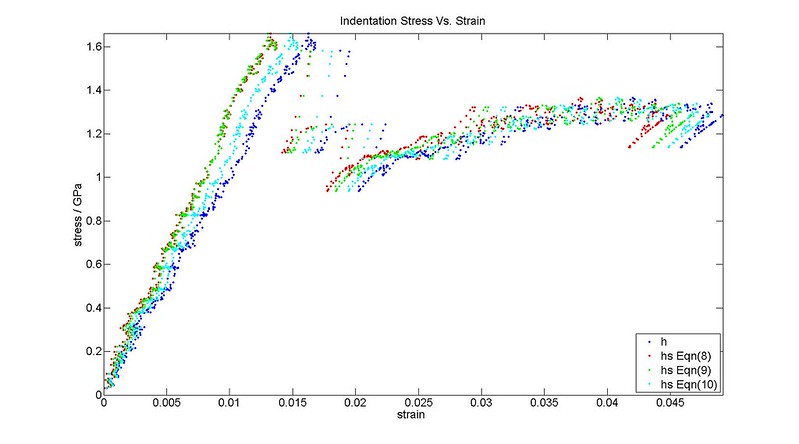
The definition of indentation stress and strain is given as from Kalidindi and Pathak (2008)
It can be shown that dividing Equation (1) by $ \pi a^2$ will give the stress-strain relationship . However this is a constitutive equation for the indenter-sample system. We would like a constitutive equation for just the sample (i.e. where ).
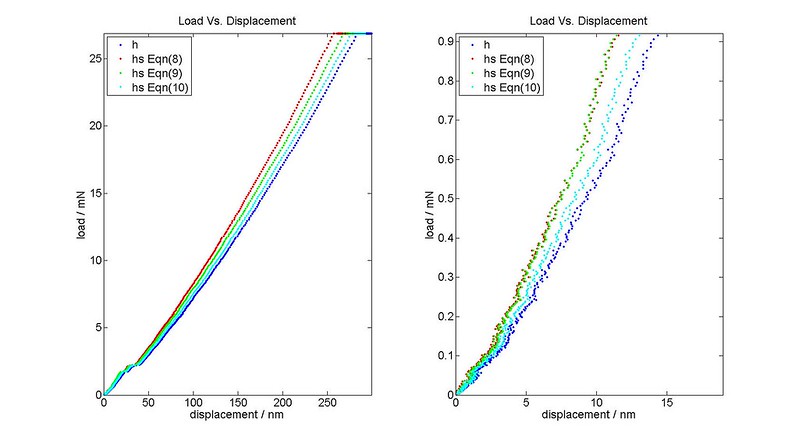
We can get there by recalling that the pressure in the indenter and sample is the same, therefore the effective stress is also; however the indentation depth, $h$, is the total displacement or characteristic of the total deformation of the indenter and sample. The effective strains of the indenter and sample depend on the indenter and sample displacements. To establish the sample strain, we must account for the indenter displacement.
We can use the idea of a compliance correction from compression testing to calculate the indenter displacement. Note that the load frame compliance is already accounted for in the measurement of $h$, but this does not take into account the deformation of the tip itself. We assume the deformation of the tip is elastic. The tip displacement is determined as a function of load by assuming the tip is indented into a rigid surface. The rigid surface curvature should reflect the curvature during the experiment. This is important when the sample has been plastically deformed because $R_{eff}$ is no longer $R_i$.
Using the following to describe a rigid, flat sample surface $E_s=\infty$, $R_s=\infty$, and $h_s=0$
If we lift the assumption that the sample surface is always flat
Additionally we will need Equation (2) and the following expression found using $S=\frac{dP}{dh}$ to calculate $R_{eff}$ at each point during the actual test
Finally, there is yet another way to calculate that is algebraically the same as the case above only uses $a$ instead of $R_{eff}$, yet produces a different value.
Here we need also derived from $S=\frac{dP}{dh}$
Let’s explore all three equations and two ways to determine where
a) Calculate from Equation (4)
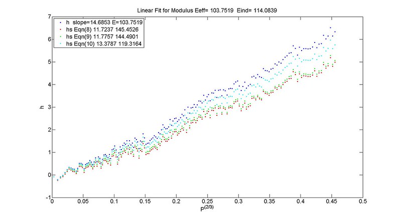
b) Calculate from $P^{2/3}$ vs $h_s$
Results
Discussion
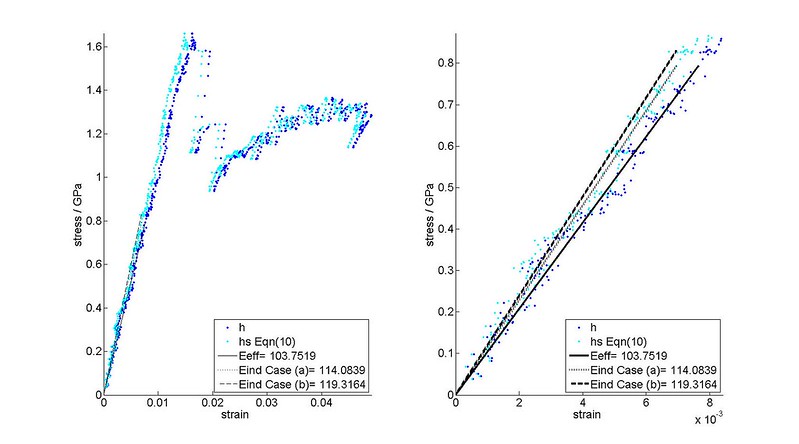
Equation (10) provides the smallest correction and closest agreement with Equation (4) for determining . It can be seen that $E_{ind}$ from Equation (4) and from the Vs. do not match (a difference of ~5 GPa). Using Equation (4) keeps the relationship between , , and consistent.
The indentation stress-strain procedure should be as follows
- Apply CSM corrections (see a later post)
- Find the zero point correction using $P, h, S$.
- Find $E_{eff}$ from the zero point corrected $P, h$.
- Find the contact radius, $a$, from .
- Find using Equations (7) and (10). Note that $P$ should be the zero point corrected load.
- Find indentation stress and indentation strain using equations (5) and (6) using $h_s$ instead of $h$.
- Plot on the indentation stress-strain plot calculated Equation (4). Note that the stress-total strain plot and will be used for optimization when determining the zero point correction.
Conclusions
- The correction while small is important in order to define the constitutive stress-strain relationship for the material system.
- Some explanation is still needed for why Equations (9) and (10) produce different results than Equation (10) and more justification needs to be provided for using Equation (10).
- Any indentation material properties (modulus, yield strength, and hardening) should be determined from the indentation stress Vs. sample indentation strain plot.
References
- Kalidindi, S.R. and S. Pathak. “Determination of the effective zero-point and the extraction of spherical nanoindentation stress–strain curves”. Acta Materialia. 2008
- Pathak, S. et al. “Measurement of the local mechanical properties in polycrystalline samples using spherical nanoindentationand orientation imaging microscopy.” Acta Materialia. 2009.
- K.L. Johnson. Contact Mechanics. New York, 1985.
- Vlassak J.J. and W.D. Nix. “Indentation modulus of elastically anisotropic half spaces.” Philosophical Magazine A. 1993.
- Vlassak J.J. and W.D. Nix. “Measuring the elastic properties of anisotropic materials by means of indentation experiments.” J. Mech. Phys. Solids. 1994.